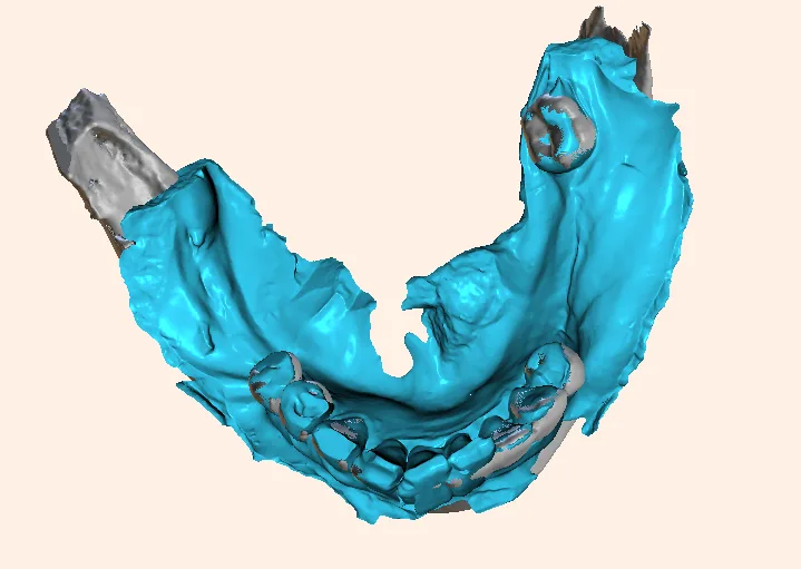
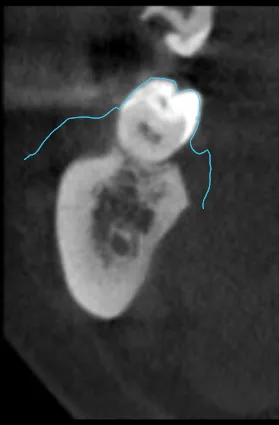
Recently, I encountered a baffling clinical puzzle: an intraoral scan refused to superimpose onto a patient’s CBCT volume. The scan in the anterior region was perfectly superimposed, but coming the posterior region, it failed. when i tried to superimpose the posterior region, the anterior region failed.
The interesting part is neither the AI, nor the manual superimposition succeeded. Sitting there watching the digital workflow grind to a complete halt, I was genuinely surprised—until a technical audit of the files uncovered a hidden culprit that most practitioners never suspect.
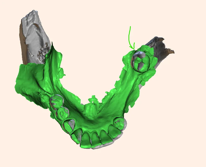
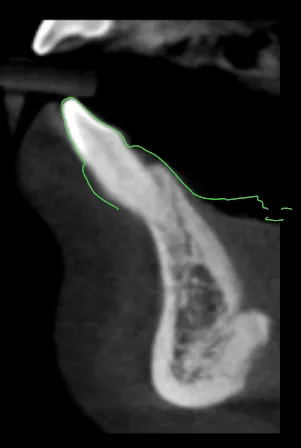
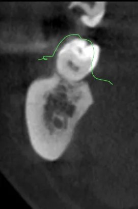
If you’ve ever tried to superimpose an intra-oral surface scan onto a CBCT DICOM volume—only to watch the software fail completely because the sizes don’t match—you know the frustration. You assume it’s patient movement, metal scatter, or algorithmic stitching drift.
But what if the problem is something much more fundamental? This is caused due to “macro-arch distortion driven by cumulative stitching drift (algorithmic linear expansion/contraction)“.
Intraoral scanners do not take a single snapshot; they stitch together thousands of individual 3D image frames sequentially. As the scanner moves from the anterior teeth all the way back to the terminal molars, tiny, imperceptible alignment errors from frame to frame compound linearly.
By the time the scan completes the full arch loop, the posterior segments have effectively “drifted” spatially.
Why it breaks CBCT superimposition?
Linear arch wraping
A CBCT scan represents rigid, true-scale bone and hard tissue. If your intraoral mesh has suffered from a few fractions of a millimeter of stitching stretch or compression across the arch, it is no longer geometrically identical to the CBCT.
The software is forced to choose: fit the anterior anchor points OR fit the posterior anchors. It cannot do both because the overall arch length of the mesh is mathematically distorted.
Feature-Poor Geometry in the Posterior Region
Anterior teeth are a tracking algorithm’s best friend, boasting sharp incisal edges, prominent line angles, and distinct curvatures that make frame-to-frame stitching seamless. Posterior teeth and molars, by contrast, present a much tougher challenge: smoother occlusal tables, high-gloss restorations, and moisture pooling create a feature-poor environment.
Dynamic Soft-Tissue Deformation
To make matters worse, human error often enters the equation. In an attempt to aggressively capture vestibular depth, operators will frequently manually retract or pull the buccal mucosa.
Because soft tissue stretches dynamically while you scan, this introduces erratic mucosal movement into an already fragile tracking zone. Deprived of stable geometric anchors, the scanner’s software begins to ‘guess’ and interpolate missing data, culminating in cumulative stitching drift that warps the terminal ends of the arch—explaining why locking in the anterior teeth instantly breaks your posterior alignment.
The Compounding Effect of Algorithmic “Guessing” and Frame Stretching
Deprived of stable geometric anchors, the software’s error-correction routines begin to interpolate or “guess” how to bridge the gap between frames. This forces cumulative stitching drift, physically stretching or warping the posterior digital mesh away from its true anatomical scale. That is precisely why matching the anterior region threw off the posterior, and vice-versa—the entire posterior arch geometry had been algorithmically stretched out of proportion.
How to Fix This?
Fallback to an Extra-Oral Model or Impression Scan
If intraoral access, aggressive cheek retraction, or moisture contamination repeatedly causes full-arch stitching drift and posterior distortion, abandon the direct intraoral approach. Take a high-accuracy conventional elastomeric impression (or pour a quality gypsum cast) and run it through an extra-oral tabletop scanner.
Because benchtop scanners operate in a controlled, stable environment without soft-tissue interference, they completely eliminate intraoral tracking errors and restore true 1:1 metric scale.
The “Cut-Out and Rescan” Technique
If you must stick with an intraoral scan, do not try to re-scan over a distorted area. Completely delete the drifted posterior quadrant from the mesh, thoroughly dry the area, and re-scan with a clean, controlled overlap anchored back to the stable anterior geometry.
Modify the Scan Path
Instead of a chaotic or single-sweep route, use the manufacturer’s validated path (typically starting on the occlusal of posterior teeth, moving anteriorly, and looping back via the lingual/palatal) to lock in cross-arch stability early.
Targeted Best-Fit Alignment
When doing CBCT superimposition, avoid using the entire arch if stitching drift is present. Restrict your initial point-based or surface-matching software alignment strictly to the local region of interest (e.g., locking onto the anterior teeth or the immediate segment where the implant/restoration is planned) rather than forcing a global full-arch match.
Other common erros to discuss
The Subgingival Margin and Finish-Line Distortion Error
When preparing teeth for crowns or laminate veneers, the location of the finish line plays a critical role in optical impression trueness. Research consistently shows that subgingival margins yield significantly lower scanning accuracy compared to equigingival or supragingival margins.
Because the scanner’s light source relies on a clear optical line of sight, subgingival boundaries are frequently obscured by gingival tissue collapse, sulcular fluid, or minor bleeding. Even with optimal retraction cords, capturing these deep, hidden margins often results in a “fuzzy finish line” or surface smoothing artifacts, making it difficult for the lab or CAD software to identify the exact margin transition.
Reflective Material and Optical Surface Artifact Errors
The optical properties of the objects being scanned—such as highly polished metal restorations, gold, or translucent zirconia—can severely compromise scan quality. Intra-oral scanners project light or laser patterns onto the tooth surface to calculate depth and coordinates, but highly reflective or translucent materials scatter this light rather than cleanly reflecting it back to the sensor.
This optical confusion generates severe scanning noise, surface holes, or false geometric projections. Consequently, scanners vary wildly in their ability to handle these difficult materials, often requiring specialized scanning strategies or anti-glare powders to capture an accurate mesh.
Anatomical Overcrowding and Space Restriction Errors
Intra-oral scanner performance is heavily dictated by oral morphology and physical maneuverability constraints. In patients with severe dental crowding, the lack of interdental spacing physically restricts the scanner tip from navigating tight embrasures and undercuts, blocking optical access to proximal surfaces.
Furthermore, compared to controlled benchtop models, operating inside a restricted oral cavity forces awkward scanning angles and longer acquisition times. This restricted maneuverability not only increases local surface errors but also forces the software to struggle with stitching frames together in tight, feature-deficient spaces.
Hardware Calibration Drift
If the scanner’s internal optics or mirrors fall out of calibration (due to thermal shifts, minor impacts, or heavy usage), the spatial relationship calculated by the sensors becomes skewed, resulting in scaled or warped digital models. Regular manufacturer calibration checks are essential.
Software Rendering and Compression
Exporting meshes or converting high-density point clouds into optimized files can occasionally introduce minor geometric smoothing or voxelization tolerances, though these are usually clinically negligible (within a few microns).
How intra oral scanners try to remain error free?
Intraoral scanners do not use an X-ray beam projected from a focal spot through an object onto a detector (which creates geometric magnification based on object-to-detector distance according to the inverse square law and divergence angles). Instead, they capture physical surface data directly using structured light, confocal microscopy, or active wavefront sampling.
The output is a 3D polygonal surface mesh (STL, PLY, or OBJ file) rendered in a virtual coordinate system where 1 unit in the software equals 1 millimeter in reality. There is no divergent projection scaling.
While magnification isn’t an issue, dimensional accuracy can still be compromised by several digital and physical factors. Hence every clinician must know that, these scanners are not error free.
Conclusion
Intra-oral scanners have undeniably revolutionized contemporary dentistry, offering speed, patient comfort, and a streamlined digital workflow. But as our recent clinical encounters remind us, a digital impression is not an infallible black box. From subtle scaling ratio mismatches and software export errors to compounding stitching drift caused by aggressive soft-tissue retraction and feature-poor posterior anatomy, digital scans are vulnerable to invisible distortions that can wreck a CBCT superimposition or a precision prosthetic fit.
Ultimately, achieving true accuracy requires looking past the “1:1 myth.” By understanding the multifactorial nature of intra-oral scanning, respecting anatomical limits, controlling moisture and optical reflections, verifying software export units, and knowing when to fall back on an extra-oral model scan—clinicians can bridge the gap between digital convenience and true clinical precision. After all, technology is only as accurate as the operator who verifies it.

A passionate dental educator with more than 13 years of academic experience, I am dedicated to making complex imaging feel simple by always starting from the basics. Technology is my playground—specializing in CBCT reporting, digital implantology, 3D modelling, and dental 3D printing innovations. Through my writing and teaching, I love empowering clinicians to bridge the gap between advanced digital workflows and everyday clinical practice.
Read more about me on the “about me” page.
- Are Intraoral Scans Actually Distortion-Free? Know this before you buy one - November 1, 2026
- Decoding TMJ Pain: Why Open-Mouth CBCT Views Are a Game-Changer in TMJ Diagnosis - October 30, 2026
- What is Dental MRI? The Future of Radiation-Free Oral Imaging - October 25, 2026